Home>>>multiplex transformer rectifer
multiplex transformer rectifer
multiplex transformer rectifer
Introduction To Product
Overview
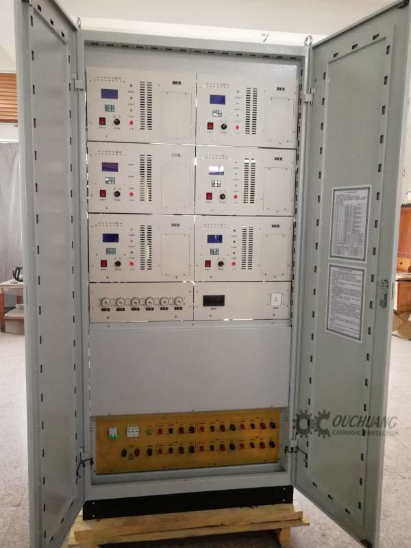
ZSHD-1 multi-channel remote transmission and remote control anti-corrosion power supply is widely used in pipes, cables, steel terminals, gates, ships, storage tanks, storage tanks, coolers and other metal structures or equipment in soil, sea water, fresh water and chemical media. The implementation of external current cathodic protection has advanced technical performance indicators, high reliability and long service life.
Main features
ZSHD-1 multi-channel remote transmission remote control anti-corrosion power supply roommate remote transmission interface, which can realize remote data transmission.
The anti-corrosion power supply system contains two completely independent potentiostat units and a switching control circuit.
The potentiostat roommate has multi-channel sub-cathodes, which can protect several protective bodies separately, and independently adjust the output current of each sub-cathode to make the potential of each protective body reach the desired value.
Main technical indicators
1. Power supply: AC single-phase AC220V±10%, 50Hz±10%.
2. Safety requirements
2.1 Insulation resistance: The insulation resistance of the film input terminal of the equipment to the shell machine is not less than 10MΩ.
2.2 Dielectric strength: The power input end of the equipment can withstand a test voltage of 1500V (effective value), 50Hz to the case, and no flashover or breakdown occurs for 1min.
2.3 Isolation withstand voltage: the equipment’s “zero position to female” terminal can withstand 750V for a new output terminal.
(Effective value: 50Hz test voltage, lasting 1min, no flashover or breakdown phenomenon occurs.
3. Range of output voltage and output current: the adjustable range of output voltage and output current is not narrower than the rated value of 1%~100%.
4. Ripple coefficient: When the equipment is fully loaded, the ripple coefficient is less than 5%.
5. Operating mode
5.1 Manual adjustment operation mode: manual continuous adjustment.
5.2 Potentiostatic operation mode
5.2.1 Constant potential control range: continuously adjustable in the range of 0mV~ -3000mV
5.2.2 Constant potential accuracy: less than 5mV
5.3 Constant current operation mode:
5.3.1 When the equipment cannot operate at constant potential for some reason, it will automatically switch to constant current operation mode.
5.3.2 Constant current setting range: 1%~100% output current rating.
5.3.3 Constant current accuracy: better than 2%.
6. Reference input impedance: greater than 1MΩ.
7. With soft start function.
8. And there is a protection potential deviation alarm function.
9. And has overcurrent protection function.
10. With self-check function.
11. Continuity test function: the device has two continuity test functions, manual control and remote control, continuity test function, the device is in an intermittent working state during the continuity test (on 12 seconds, off 3 seconds).
12. Display function: It can detect voltage, output current, tube ground (protection) potential, and AC input voltage.
13. Equipment operation selection: select any potentiostat unit to be put into operation by the switch. The equipment is equipped with an interlock device, and the two textile potentiometer units are put into operation at the same time.
14. Data remote transmission interface connected with RTU: The equipment realizes remote monitoring and control of computer operating parameters and operating status through the data remote transmission interface.
15. Lightning protection: The input and output terminals of the equipment are equipped with lightning protection circuits, and comply with the provisions of IEC1024.
16. Anti-interference ability: The reference input has the ability to resist AC power frequency interference and instantaneous interference.
17. Remote control setting function: When the RTU “remote control setting signal” is transmitted to the potentiostat “RS” input terminal, and “RS” is transformed into an output current greater than 3.8mA, the set potential of the remote control cathodic protection system is determined by Remote control. When the RTU “remote control given signal” is transmitted to the input terminal of the potentiostat “RS”, and “RS” is transformed into an output current less than 3mA, the given potential of the remote control cathodic protection system is controlled by the internal “control adjustment” Potentiometer control. Controls. When the RTU “remote control given signal” is transmitted to the potentiostat “RS” input terminal, RS is transformed into a standard industrial signal outputting 4mA~20mA, and it is transformed into 0~-3000mV on the working machine “remote control given signal” For a given potential signal, the conversion error should not be greater than 0.3%.
18. Remote control switching function: When the “RS” input terminal of the potentiostat receives the “A machine selection signal” and the “RS” output terminal is transformed into a high-level pulse signal with a pulse width of 1S and an amplitude of +24V, the A machine Should be able to be put into work, B machine exits operation; when the potentiostat “RS input terminal, receives “B machine selection signal” and “RS” output terminal is transformed into a high-level pulse signal with a pulse width of 1S and an amplitude of +24V , Unit B should be able to be put into operation, and unit A should exit operation. The indicator light should have corresponding instructions.
19. Remote control switch function: When the “RS” input terminal of the potentiostat receives a high-level pulse signal with a pulse width of 1S and an amplitude of +24V at the “RS” output terminal of the potentiostat, the system should be able to shut down normally.